MONARCH 9820 PRINTER DRIVER

| Uploader: | Voodoot |
| Date Added: | 6 July 2010 |
| File Size: | 45.71 Mb |
| Operating Systems: | Windows NT/2000/XP/2003/2003/7/8/10 MacOS 10/X |
| Downloads: | 74151 |
| Price: | Free* [*Free Regsitration Required] |
What's missing? Tell us about it.
Loosen locking screw and set eccentric at the recent 16 supplies printed. Set the Port for "External" if using the external parallel port or the external Ethernet card. rpinter
Adjust cutter as necessary. Ensure the stacker-to-knife harness is properlyconnected.
MONARCH SERVICE MANUAL Pdf Download.
The interface is incorporated in the microcontroller and has DIP switches to set communications parameters. Send a packet you know has no syntax errors.
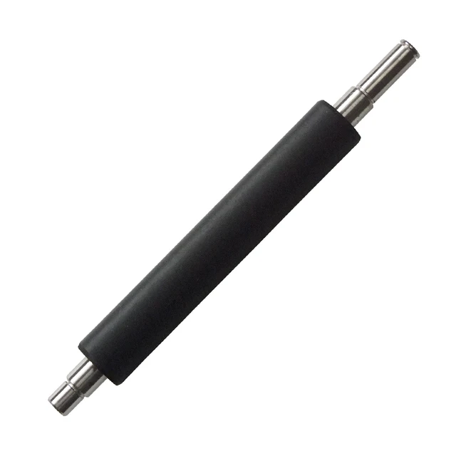
Page 7 Figure B- 4. The messages and there meaning are shown below. Unlatch the bearing block latch on each side ofthe platen roller by inserting a small bladescrewdriver between the latch and the platenframe.

The bar-code field will be replaced with a grey-scale pattern instead of printing a code that would scan with incorrect information. Confirm supply sensor operation. Release wires from loop holder2.
CN 14 Figure B- Remove the rivot from bearing block onprinthead latch side. The DIP switches can be set manually priter the user or through software control.
Printer | Avery Dennison
Are the DIP switches set properly to match communication values and existing supply? Don't show me this message again. Check to ensure tags being used do not exceed0. Clear a work area approximately four feet wide. CN 6 Transformer Output Pow Perform sensor display service test. International Manuals Download the latest international manuals for printer manuals.
Monarch 9820 Printer User Manual
Ensure the stacker-to-knife harness is properly connected. Enter text from picture: The old lower transport assembly should now beheld in place by the four remaining plastite screwson the rear main frame Send a packet you know has no syntax errors.
Cut multiple is outside range 0 to Some printers only support one type of supply indexing method. Use Sendfile Version 2. All of the harnesses are identified with partnumbers and must be attached to the sensor board Figure 1 - 2.
Plastic Cover Printers Description and Qty. Remove three printhead module screws, asshown in Figure Press Clear and try to continue. Help documentation within the application. The next transition edge of importance is the TOF.

Comments
Post a Comment